

Co-design for injection molding is the joint engineering of a plastic part by the customer who conceived it and the company that will build the mold and mold the part. It checks manufacturability right from the drawing, selects the material, mold and process, and removes problems before series production, when every change still costs far less. The result is a part that runs in production without downstream fixes, with shorter lead times and lower costs.
Co-design for injection molding: what it is
Co-design (cooperative design) is a working partnership between the originator of a project and the company that produces it. This shared engineering aims to optimize every production step as well as the cosmetic, physical, mechanical and chemical properties of the product. Co-design matters not only for new parts but also for improving existing ones. In this article we look at what characterizes co-design for plastic injection molding, focusing on the development of a new product.
Why co-design matters in injection molding
Co-design is essential to support the customer in developing a thermoplastic part. A careful upfront analysis of the component makes it possible to produce a part that is technically sound and meets the needs of the customer and its target market. This support covers every stage of development and is what ensures thorough part engineering.
The key steps toward a finished part that needs no further improvement are:
- feasibility study
- industrialization
- cost analysis
- process engineering
- verification of functional and quality requirements
- pre-series molding
- final part approval.
Through these steps, co-design helps identify potential issues with the part early in development. Addressing them before series production brings some important benefits:
- first, development and processing time is reduced, because problems that would otherwise surface in series production of a part considered finished, but which in fact is not, are solved upstream
- productivity improves: there is no need for unplanned design, tooling and process corrections downstream caused by design errors, which could lead to production downtime
- finally, as a result of the first two points, production costs are lower. A production stoppage is a significant cost in itself, on top of tooling and process changes that are expensive and sometimes not even feasible.
The steps in developing a new product through co-design
A new product starts with its design. The company that conceives the part usually provides a concept sketch or a technical drawing (2D or 3D). The 3D CAD model is then used to identify and solve technical and economic feasibility issues.
Before any tooling is built for prototypes or production parts, the DFM report (design for manufacturing) plays a key role. It makes it possible to identify and correct design errors, simplify the production process, find the best manufacturable solutions and reduce production cost and lead time.
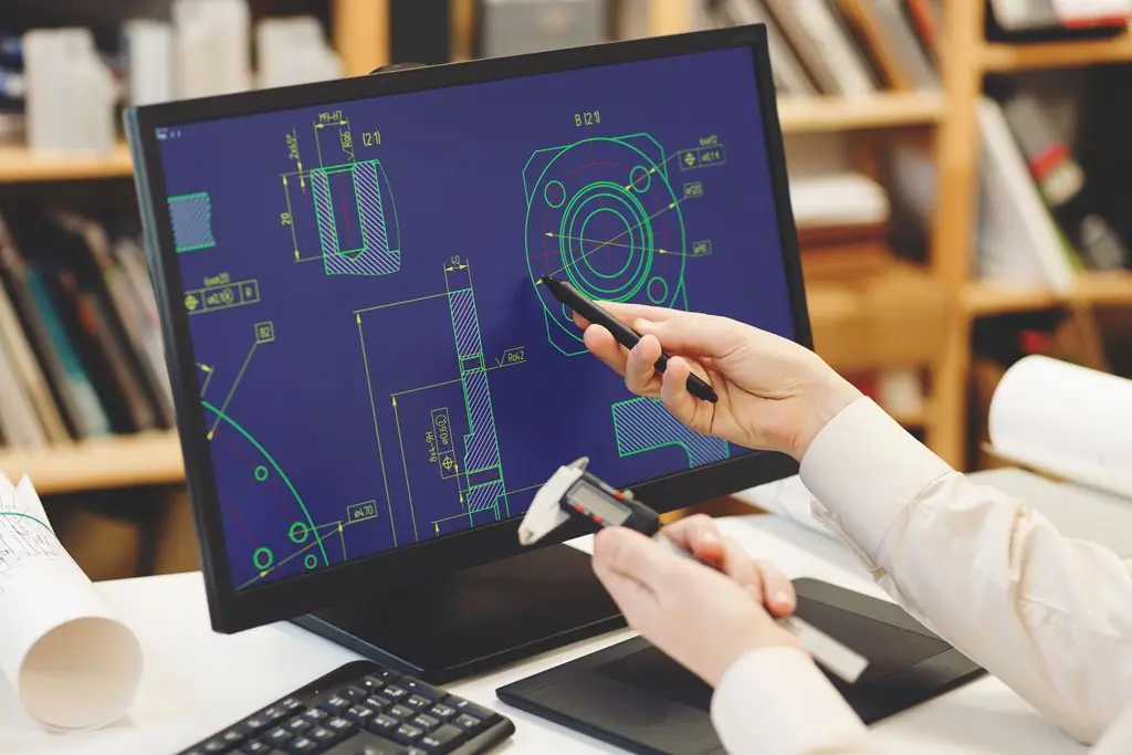
Once the technical aspects have been analyzed and any problems solved in CAD, development moves on to the next steps.
Prototypes and final steps
After the DFM review, the next step is usually 3D prototyping, which gives a visual, physical model of the part and a further feasibility check. Since there are several 3D printing technologies, it is important to choose the one that best suits the part: a co-design project makes it possible to compare additive manufacturing processes and recommend the most suitable one. Bemar Plast produces FDM, SLA and MJF prototypes through a qualified service bureau in Italy and remains the single point of contact from prototype to production (see 3D printing and prototyping).
The next phase defines the materials, tooling and process solutions that will optimize production cycles for the final part:
- tool design, that is the injection mold design and its optimization: for example the choice of mold material (usually steel or aluminum), the number of cavities, the gate type (such as submarine/tunnel gate or fan gate), thermal analysis and cooling circuit design, and the study of part geometry (shapes, wall thickness, draft) and cosmetic finishes where needed
- selection of the most suitable press clamping force and balanced filling
- selection of the most suitable thermoplastic material, based both on industry experience and on objective data about the polymer, such as its rheological behavior. For technical parts, engineering plastics such as PA (nylon) or POM (acetal) are often evaluated.
Critical issues in a product
Throughout this article we have referred to critical issues that can emerge from the feasibility study. They can concern the part, but also the tooling and the process. Co-design for injection molding makes it possible to identify them before they occur.
So what are these issues? Here are some of the most common, relating both to the part and to the process:
- a part design unsuited to injection molding of thermoplastics
- limits and issues in the molding process, such as wrong parameter settings, melt temperature or injection speed
- visible defects on the part, such as sink marks or warpage, flash, jetting, flow marks, drag marks on ejection or other surface imperfections
- mold problems, such as incorrect mold temperatures, inadequate cooling, unsuitable steels or alloys, poor finishing, issues with cavities or ejectors
- unsuitable raw material, such as a polymer, additives or fillers that do not fit the application.
Simulation and analysis: tools and software
To spot problems during the feasibility study, there are tools and software that highlight design issues starting from the part's 3D model.
These are the tools and software typically used to assess the feasibility of a project and highlight problems at both product and process level:
- 3D modeling of part and mold with software such as CATIA, NX and Rhinoceros
- the DFM report described above
- FEA (finite element analysis), a numerical simulation of the part that identifies stresses, deformation and weak points under load, avoiding costly changes later on
- CAE (computer-aided engineering), the set of computer simulations, FEA and mold flow included, used to detect engineering and design errors in the part
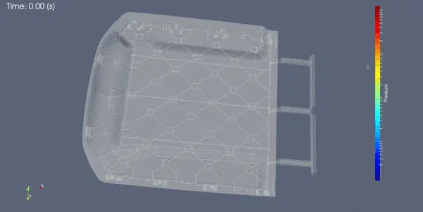
- mold flow simulation, which checks how the thermoplastic behaves as it fills the mold: it reveals flow problems, weld lines, air traps and warpage and helps optimize molding. At Bemar Plast, mold flow simulations are carried out with specialized external partners
- rapid 3D prototyping, to obtain physical prototypes before the mold is built
- 3D scanning of pre-series parts, to check directly whether the real part deviates dimensionally from the CAD model
- pilot or prototype molds, where needed, and the pre-series parts made with them
- digital reverse engineering of mold and part, for existing products that need improving.
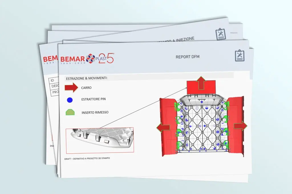
Image: Brochure psd created by lcd2020 – www.freepik.com
Conclusion
Co-design is a complex but essential process for reaching series production of a well-engineered part. Bemar Plast provides this support thanks to experience built up in injection molding since 1995 and in developing new projects: from feasibility and mold design through to series production in our injection molding plant in San Giovanni Ilarione, near Verona, Italy.
Frequently asked questions
What is co-design in injection molding?
Co-design is the joint engineering of a plastic part by the company that designed it and the molder that will produce it. The customer brings the functional, cosmetic and market requirements; the molder brings its know-how on materials, molds and process. Together they arrive at a part that runs in production without downstream fixes.
What is a DFM report for injection molding?
A DFM (design for manufacturing) report is a feasibility review of the part's 3D model, carried out before the mold is built. It flags uneven wall thickness, insufficient draft, undercuts and other critical features, and proposes the changes that make the part moldable reliably and cost-effectively.
Why involve the molder early in the design phase?
Because fixing a mistake in CAD costs far less than modifying a finished mold or stopping production. Co-design brings part, mold, material and process issues to light early and cuts development time, scrap and cost.
What role does 3D printing play in co-design?
3D printed prototypes let you check form, fit and assembly before you invest in a mold. Bemar Plast produces FDM, SLA and MJF prototypes through a qualified service bureau in Italy and remains your single point of contact from prototype to production: see our 3D printing and prototyping service.
Does Bemar Plast design the mold as well?
Yes. We design new molds in-house and have them built by partner toolmakers in Italy or China, as the customer prefers, to our technical specification; design approval, tryout and maintenance stay with us. Learn more about our injection mold design service.