

Thermal thickness analysis is a numerical calculation that shows which areas of a plastic part stay hot longest and therefore freeze last. It is run early in injection mold design to choose the gate location and to spot excessive wall thickness that would cause sink marks, voids and longer cycles.
When you start working on a new injection molded plastic part, the feasibility study plays a crucial role. Several tools and types of analysis can be used in the early stages of a project, and co-design between the customer and the molder is one of them. In this article we focus on one specific tool: the thermal thickness analysis of a part.
Thermal thickness analysis: what it is
First of all, what does thermal thickness analysis involve?
It is a numerical analysis of the geometry of a polymer part that will be injection molded. For every area of the part it calculates the thermal thickness: an equivalent thickness that accounts not only for the wall itself, but also for the heat that builds up in ribs, bosses, fillets and wall intersections. Two areas with the same nominal wall thickness can cool in very different ways.
The results help you optimize the part and mold design from the very first stages. Inaccurate design decisions, or defects that go unnoticed and are not removed early (such as thermally unbalanced areas or walls so thick that they show sink marks once molded), become more and more expensive to fix as the part moves toward production.
In particular, the analysis is used to optimize one aspect that is essential for good moldability: the location of the gate (or gates).
The calculation lets you quickly identify the best gate location (or locations) in the mold.
What it is used for
In practice, thermal thickness analysis keeps you from ending up with a poorly optimized mold that produces defective parts. In those cases, the mold often needs rework afterwards, which can be quite expensive and could have been avoided with more careful design.
More specifically, the analysis helps you:
- find areas at risk of sink marks and internal voids, where the material keeps shrinking after the surface has already solidified
- reduce thermal imbalances that, through uneven cooling, can cause the part to warp
- see where cooling time is concentrated: it grows roughly with the square of the wall thickness and directly affects cycle time.
Thick sections are especially critical with semi-crystalline polymers such as PP or POM, which shrink more than amorphous polymers.
In short, running a thermal thickness analysis early cuts the cost, time and waste involved in bringing a product to production, because the part and mold design are optimized from the start.
So how is this parameter calculated? Let's look at the details.
Software tools for thermal thickness analysis
The calculation described in this article is carried out with dedicated CAE simulation software. You enter the part geometry (for example an STL file) and some properties of the solid polymer, such as density in kg/m³ and specific heat; the software then runs a series of calculations that return the thermal thickness of every area of the part.
The calculations can take up to a few hours, depending on the size and complexity of the part. The software then presents the results as color maps.
One tool for this kind of analysis is BestGate by Argo Srl, which delivers results fairly quickly.
Thermal thickness analysis: reading the results
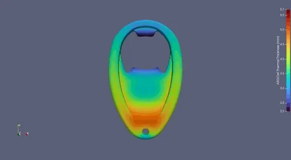
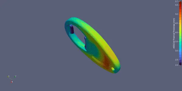
The maps show thermal thickness, in millimeters, on a color scale. Light blue and blue areas have a low thermal thickness: they cool, and therefore freeze, first. Orange and red areas are the thermally thickest and freeze last.
The gate should be placed as close as possible to the areas that freeze last, that is the red ones. The melt then flows from thick to thin sections, and holding pressure can compensate for shrinkage before the gate freezes off. If you gate into a thin area instead, it freezes early and the thick sections further away are left without packing, with a risk of sink marks and voids.
When the map shows isolated red areas, or red areas far from any feasible gate location, it is worth changing the part design: core out solid sections, even out wall thickness, make ribs thinner than the nominal wall. Identifying these issues is essential when designing an injection mold.
In the example below, the BEO bottle opener designed and manufactured by Bemar Plast, the thickest areas are in the lower part, near the hole.
Conclusions
Thermal thickness analysis is a valuable tool in the early design stages of an injection molded product. It gives useful information to the part designer as well as to toolmakers and molders, because it lets you optimize the part from the start and avoid unpleasant and costly surprises in series production.
Bemar Plast designs molds in house and has them built by partners in Italy or China, at the customer's choice; filling simulations are run with external partners. To find out more about this kind of analysis, or to assess the feasibility of a new part, see our pages on injection mold design and plastic injection molding, or get in touch with our engineering team.
Frequently asked questions
What is thermal thickness analysis?
It is a numerical analysis that calculates the thermal thickness of every area of an injection molded part, meaning how long that area stays hot after injection. The result is a map that separates the areas that freeze first from those that freeze last.
Where should the gate be located?
As a rule, as close as possible to the areas that freeze last, which are the thermally thickest ones. The melt then flows from thick to thin sections, and holding pressure can compensate for shrinkage before the gate freezes off.
Which defects does it help prevent?
Mainly sink marks and internal voids in sections that are too thick. It also helps reduce thermal imbalances that can cause warpage and shows which areas drive the cooling time, and therefore the cycle time.
How is it different from a mold filling simulation?
Thermal thickness analysis only considers part geometry and the thermal properties of the material, so it is faster and suited to the early stages of a project. A filling simulation models how the polymer flows through the mold: it is more complete, but needs more data and more time.
Does Bemar Plast design molds in house?
Yes. Bemar Plast designs molds in house and has them built by partners in Italy or China, at the customer's choice; filling simulations are run by external partners. See our injection mold design page for details.